Cloches GFM A - Dispositif de percement des orifices de périscope
Lien-s partie Dico :
Bonjour à tous
la question restait posée de la méthode utilisée pour le percement de l'orifice destiné au périscope sur les cloches GFM. Ce percement devant impérativement être dans l'axe horizontal afin de permettre l'utilisation du périscope ne pouvait se faire q'une fois la cloche en place.
Une partie de dispositif existe bien au Simserhof (photo sur la page ) mais il est trop incomplet pour permettre de comprendre la méthode utilisée pour garantir l'alignement.
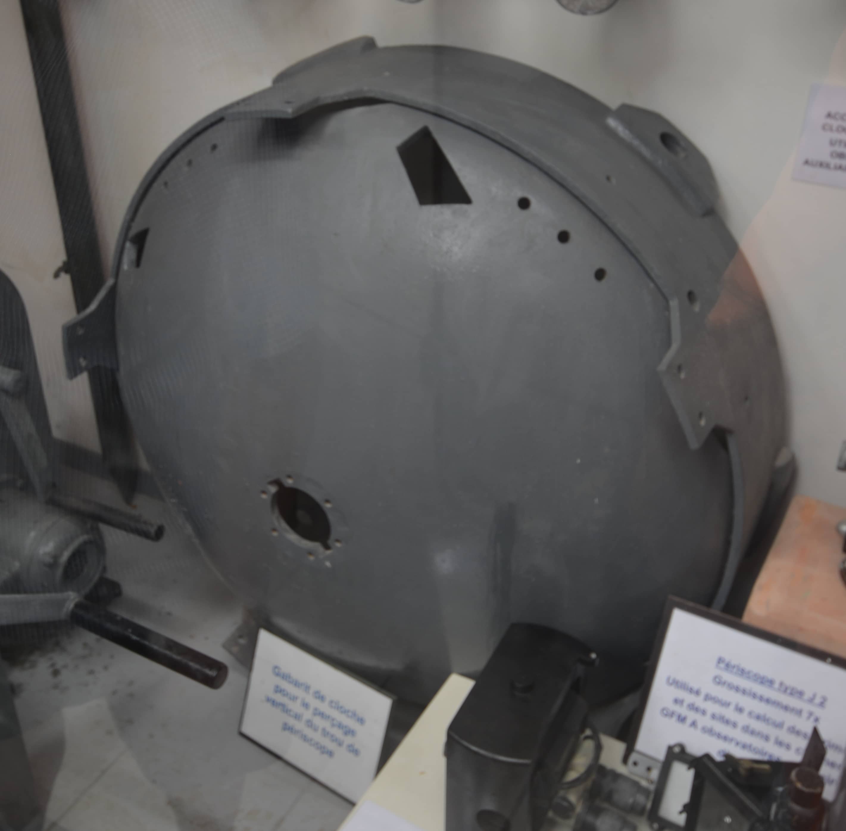
Un second dispositif existe au musée de l'ouvrage de Fermont et celui-ci donne déjà des pistes plus sérieuse sur la méthodologie employée (Photo ci dessous)
Ce système est composé d'une calotte et d'une collerette. Il devait être mis en place et bridé sur la cloche à l'aide de vis à pas non métrique (trous filetés de gros diamètre en partie basse de la collerette).
Une fois le dispositif en place, un système de réglage devait permettre avec précision l'alignement vertical de l'outil de perçage.
Reste maintenant à trouver de la documentation ou des éléments complémentaires à ce support.
Cordialement, Pascal
Hello Pascal
There is one speculation.
The hole template on the picture has a quite small diameter. I think that is for boring from inside of the cloche. Because you need to bore some parts of the hole from inside.
I see two parts: the circular ring and the calotte.
Circular ring
If I encase some liners to the bigger holes of the ring and to the holes at the corners of the orifices of the cloche also, maybe it's possible to grip the circular ring inside.
Calotte
Now I can screw the calotte to the circular ring. And after that I cen screw boring machine to the calotte.
Is it possible to check any dimensions of the ring and calotte?
Best regards
Michal
Hello Zvon
Your speculation is really interesting, i supposed (a bit to fast) that this was to be put in place on the outside of the cupola. You're right, first of all, we have to check the dimensions of those two pieces, then we will know if it this sytem was intended to be used inside or outside the cupola.
I will checkwe can find such assembly to measure it and try to find out the way it was used.
I'll keep you informed
Best regards, Pascal
Hello Zvon
I finally have a doubt about the object in the photo in the first message. This could in fact be the protective layer added in some cupolas to avoid the Hopkinson effect and not the 'gagabrit de perçage ' as described on the label.
Best regards, Pascal
Hello Pascal
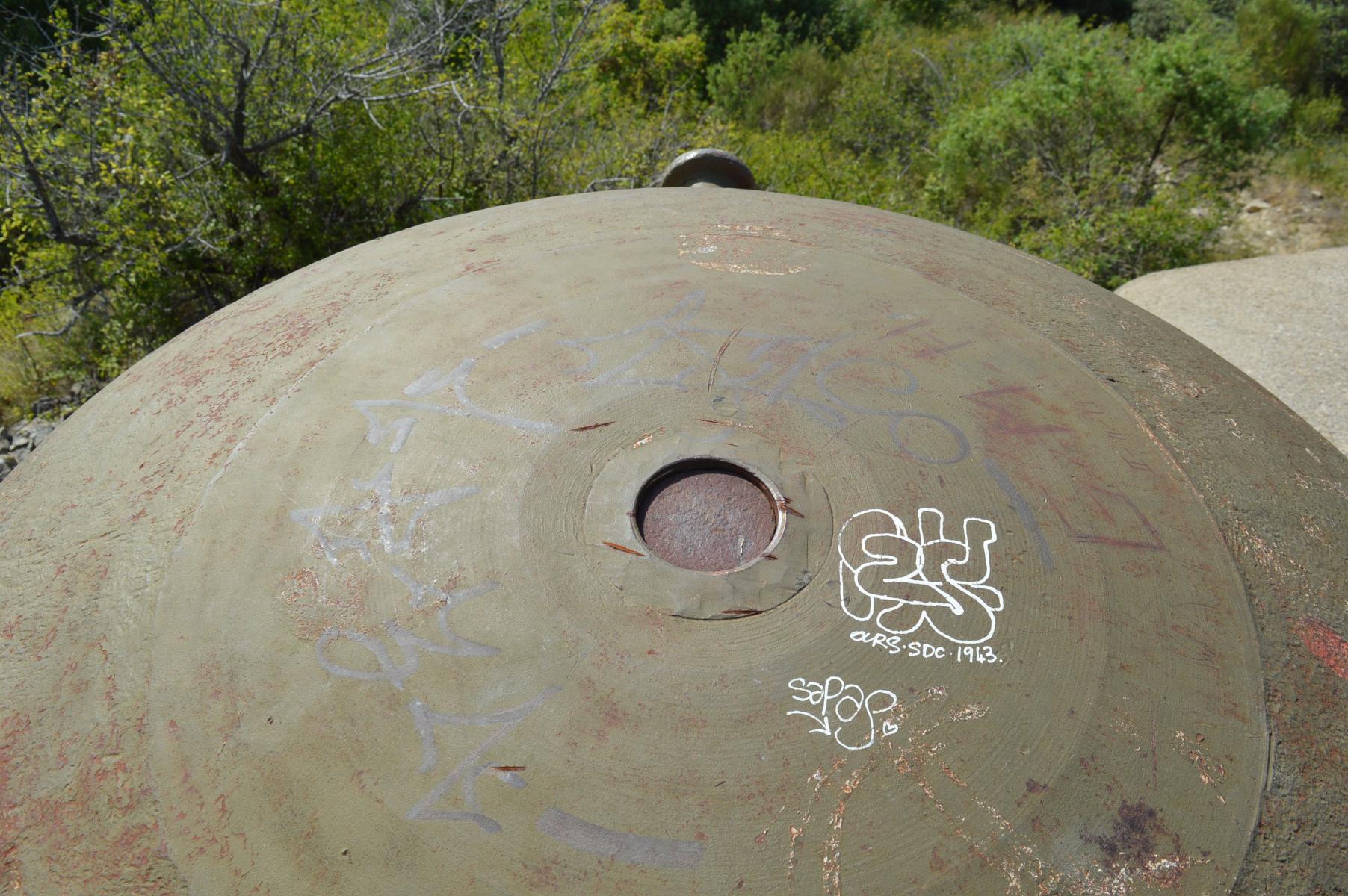
Is it sure, that the complete hole for periscope was boring after placing of the cloche to the shaft? Or there were only some modifications of finished holes? For example precise ring on the top of the hole?
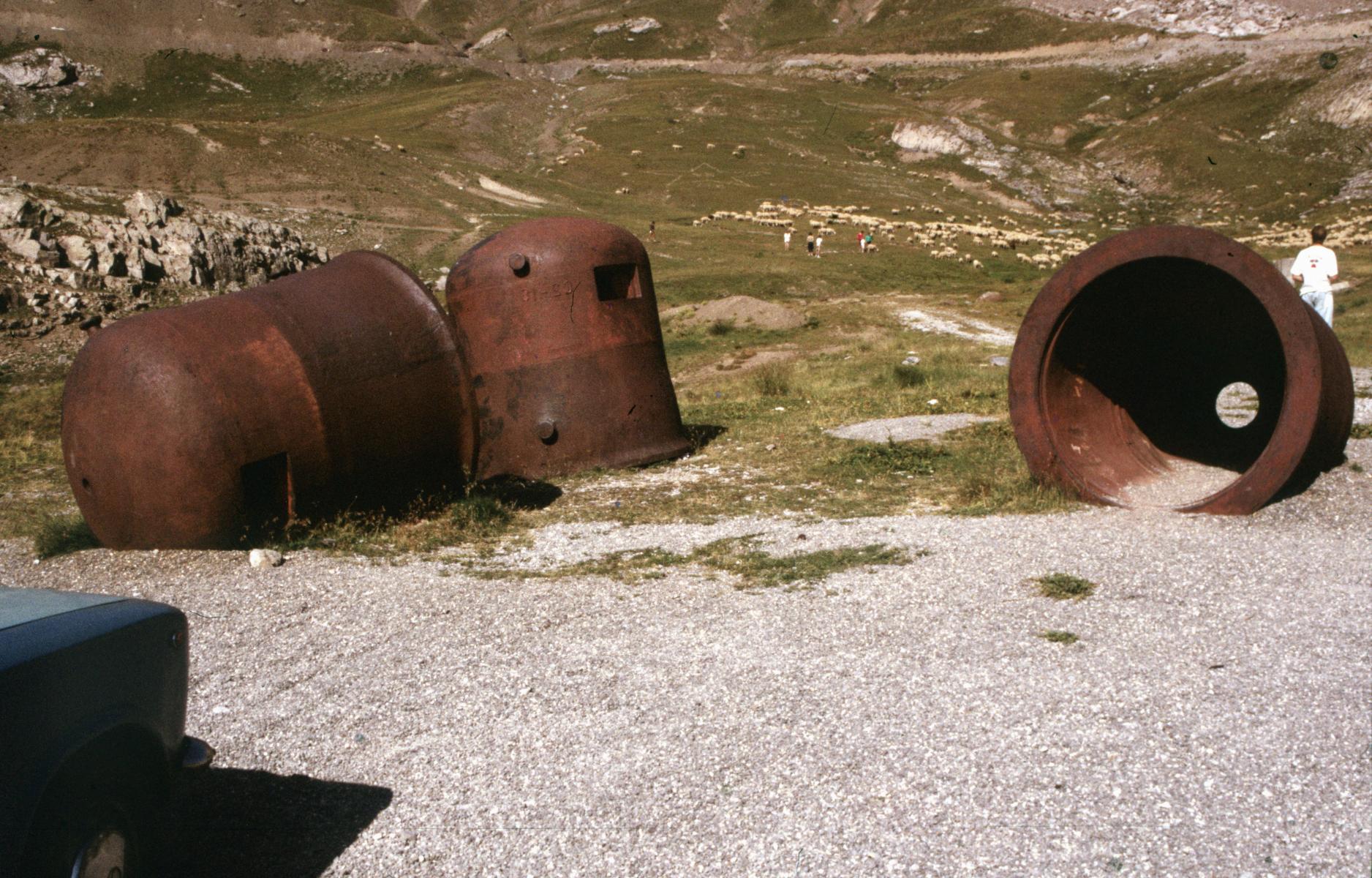
Because I see these holes for periscopes at the cloches near Restefond casern, which didn’t were placing.
I know some calculation for experimental reboring of one Czechoslovak cloche. Adjustment of the boring machine = 8 hours, boring = 5× 8 hours, reserve = 8 hours.
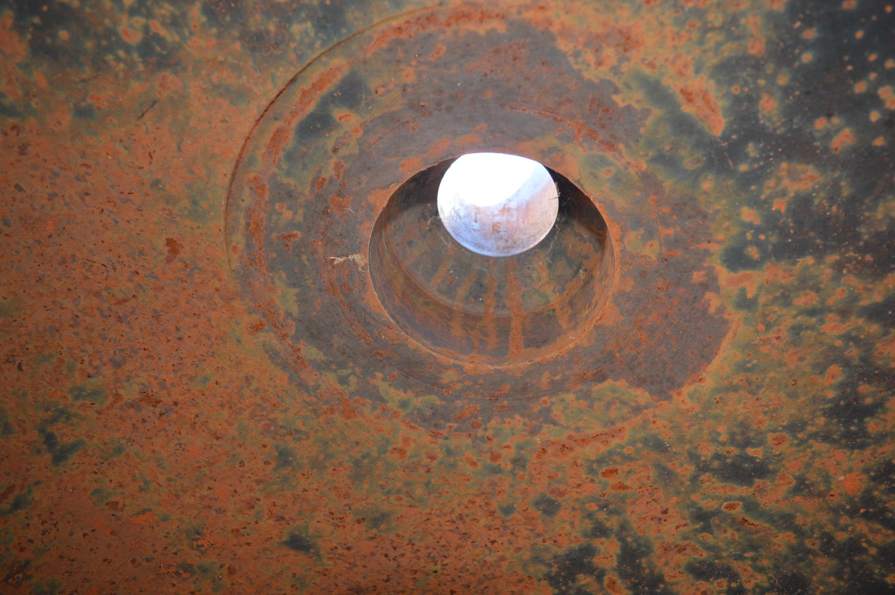
And it’s very simpler and cheaper to bore all the shape of the hole at factory and adjustment the cloche with vertical axe to the shaft, than by contraries. If you see photo from inside of cloche B5 Plan Caval, there is a quite wide machined area. And sometimes outside is bigger area. Is it possible to make it at field conditions? And how I make the hole from inside for artillery periscope (e. g. Pic de Garuche),is internal coat?
There is no problem to adjust cloche at the shaft with vertical axe. All you need are:
engineering bubble tube (on the photo is bubble tube with 0,17 mm / 1 m),
3 sets of the metal plate templates.
From 1936 to 1938 we used metal plate templates,oneincluded 2× 20 mm thickness, 3× 10 mm, 1× 5 mm, 1× 3 mm, 2× 1 mm, 1× 0,5 mm. And with this method we mounted cloches from 10 960 kg (height 200 cm) to 65 500 kg (height 460 cm).
This method allows deviation just about 0,4 mm / 1 m. Thereafter for periscope J 2 (height 0,79 m) is deviation from vertical axe about 0,33 mm. For periscope F 1 (height 0,625 m) is deviation from vertical axe about 0,26 mm. Is it possible to make the same deviation with boring at field conditions?
I think there is more questions than answers.
Best regards
Michal
Dernière modification par Pascal le 17/01/2024.
Hello Zvon
I fully agree with the fact that it was easier to do the machining required for thoses holes in factory than on the field. This operation was probably required by a difference in dimensions between holes already done at factory and the effective size of the periscope support.
It seems that the boring (or reboring?) operation was only ordered for cloche GFM A. I have not the answer as the list or orders from SEMG to Lalgrange indicates that cupolas type A from Nord-Est and Sud-Estconcerned without indication about the number of items to work on.
This could concern as well all the cupolas as just a part of those, may be only those dedicated to one periscope (F1, F2,J2). One thing would be to know which part of the hole was concerned, the whole hole and the upper and lower engaging shoulder portions or just one of those ?
We will have to look for documents in SHD about this operation to find out what it was exactly. This would help to understand if he operation was done from inside, outside or both sides of the cupola.
Waiting for this, it is obvious that the measurement of the 'gabarit de percage' exposed in Simserhof museum would help to inderstand how it was used and give a part of the answer
Still more questions than answers for the moment.
Best regards, Pascal
Hello all
We should not forget that the vast majority of GFM A cloches were manufactured and installed between 1929 and 1933. F1 or F2 périscopes were simply not considered at that time. The initial GFM manufacture drawings were not including any périscope hole !. This is why boring on site was later on required to adapt the F1,F2 or J2 devices on cloches already in place for several years. This was not required for B type cloches (and furthermore for Czech zvon which are even later) as they were designed in 1934 and manufactured at a time in which installing infantry periscopes was already considered. These holes on B type have been most probably drilled at manufacturîng stage.
The Lagrange market, placed in 1937, was actually covering most of the A type cloches (909 of them). Absolute verticality was not required as far as I’m concerned, as F1 and F2 périscope are basic infantry observation devices not requiring precision whereas the J2, real artillery measurement mean, was equiped with a verticality correction device allowing à perfect setting. All three devices have the same tube diameter, compatible with the holes drilled for F1/F2 by Lagrange, the only difference being the fixation mount of the J2 which is more complex, requiring (at least at the initial step) an internal supporting frame. 107 of these internal frames - not to be mixed up with anti-Hopkinson protection - for future J2 cloches were ordered a year later to the Bignier and Collin companies.
More generally, in situ modifications of cloches or turrets have been quite common in the Maginot Line in the later year in an attempt to correct initial shortcomings. Some exemples : reboring of the JM turrets walls to convert them into AM turrets (done on the 61 turrets), conversion of GFM A cloches to GFM B, conversion of JM cloches to AM cloches… Some french companies were quite skilled in this field (Lagache & Glazmann, Lagrange, etc) but started too late.
Best regards
Jean-Michel
Hello Jean-Michel and Pascal
I understand. I've come from this sentence on the page: "Une fois les cloches installées et scellées, il sera procédé à partir de 1937 au percement du trou en toiture destiné à la mise en place du périscope F1 ou F2. Ce choix s'explique par la nécessité de disposer d'un percement absolument aligné verticalement, ce qui n'aurait pas été possible si il avait été réalisé avant le pose de la cloche, celle ci pouvant avoir un gite de quelques degrés."
Thanks for your informations.
Best regards
Michal
Dernière modification par jolasjm le 17/01/2024.
Hello Michal
Yes, I will adjust a bit this sentence which is misleading.
You did very rightfully point out the fact that at least on cloche GFM A stored at Restefond was already having a périscope hole before installation. This is in fact coming quite nicely in support of my preceding points: the Restefond and Granges-Communes entrance blocks and Restefond B2 GFM bells have been ordered very lately in 1938 after décision was taken to accelerate again the construction, at a timeall GFM cloches were supposed to be equiped with périscope holes. These specific holes have for sure been made at manufacturing stage. Only 3 orders were placed after the initial 1929-1933 deployment, specifically assigned to the Alps in 1936, 1938 and 1939.
Best regards
Jean-Michel
Vous ne pouvez pas participer à ce fil de discussion, seuls les utilisateurs inscrits peuvent y répondre ou y contribuer.
S'inscrire sur le site est gratuit, rapide et sans engagement.